-->
What is Synchronous Motor (सिंक्रोनस मोटर)

What is Synchronous Motor (सिंक्रोनस मोटर)

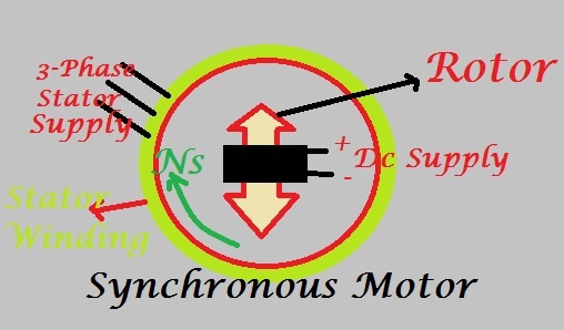
Synchronous Motor is a type of  three-phase AC motors which run at synchronous speed


Applications of Synchronous Motor: 
1.Synchronous motors are used for constant speed application.
2.Synchronous motor operates at leading power factor hence it can be used for power factor improvement. 
3.Some of the applications are as:in driving low speed compressors, slow speed fans, pumps, ball mills and metal rolling mills.
Construction of Synchronous motors:-
SM
  • A three-phase stator almost like that of an induction motor. Medium voltage stators are often used.
  • Field excitation is provided on the rotor by either permanent magnet or electromagnets with number of poles equal to the poles of the RMF caused by stator.
  • Synchronous motors works on the principle of magnetic locking between rotor magnetic field and stator magnetic field(RMF).A wound rotor (rotating field) which has the same number of poles as the stator, and is supplied by an external source of DC 
  • Both brush-type and brushless exciters are supplied by the DC source. The rotor current establishes a north/south magnetic pole relationship in the rotor poles enabling the rotor to “lock-in-step” with the rotating stator flux.Once the magnetic locking occurs,synchronous motors will run at synchronous speed in accordance with the formula:Ns=120f/p
  • But if the rotor has not got any initial rotation and the speed of stator magnetic field is very high then the situation is different.
  • N pole of RMF will obviously gets attracted to S pole of rotor and will start to move in same direction.But since rotor has got some inertia this starting field will be very low.
  • By this time the S pole of the RMF will be replaced by the N Pole. So it will give repulsive force.Therefore, rotor will be unable to start. Therefore, synchronous motor is not self starting.
  • There are different methods of starting of synchronous motor which are as below:-i).Motor Starting by Reducing the supply Frequency                                                            ii)Motor Starting with an External Motor) iii)Motor Starting by Using damper (Amortisseur) Winding
1.Motor Starting by Reducing the supply Frequency:Synchronous motor is not self starting.If the rotor has not got any initial rotation the situation is different.N pole of RMF will obviously gets attracted to S pole of rotor and will start to move in same direction.
    But since rotor has got some inertia this starting field will be very low.By this time the S pole of the RMF will be replaced by the N Pole. So it will give repulsive force.

    Therefore, rotor will be unable to start.If the rotating magnetic field of the stator in a synchronous motor rotates at a low enough speed, there will be no problem for the rotor to accelerate and to lock in with the stator’s magnetic flux .
      The speed of the stator magnetic flux can then be increased to its rated operating speed by gradually increasing the supply frequency up to its normal 50Hz value.
      But there's an enormous problem: Where from can we get the variable frequency supply? The usual power supply systems generally regulate at fixed frequency.
        We now have the rectifier- inverter and cycloconverters, which may be used to  convert a continuing frequency AC supply to a variable frequency AC supply.
        2. Motor Starting with an External Motor:- The method of starting a synchronous motor is to attach an external starting motor (pony motor) to it and bring the synchronous machine to near about its rated speed .In this type of motor a prime mover can be used to start this motor i.e an external motor can be used to start this motor.
        In this method, the shafts of SM and the external motor are attached together.Then the output of the synchronous machine can be synchronised or paralleled with its power supply system as a generator, and therefore the pony motor are often detached from the shaft of the machine or the availability to the horse motor are often disconnected.
          Once the small motor is turned OFF, the shaft of the machine slows down, the speed of the rotor magnetic field falls behind net speed, momentarily and the synchronous machine continues to operate as a motor.
          3. Motor Starting by Using damper (Amortisseur) Winding:-Amortisseur/Damper Winding are nothing but set of bars which are present in the field/rotor.When the stator of such a synchronous machine is connected to the 3-Phase AC supply, the machine starts as a 3-Phase induction motor due to  the presence of the damper bars, a bit like cage induction motor. 
            Just as within the case of a 3-Phase cage induction motor, the applied voltage must be suitably reduced so on limit the starting current to the safe rated value.

            Once the motor picks up to a speed near about its synchronous speed, the DC supply to its field coil is connected and therefore the electric motor pulls into step to runs at its synchronous speed.
            In this method motor first rotates as a 3-Phase induction motor then after reaching to 95% of the synchronous speed, the dc breaker for field excitation is switched on and therefore the field current is gradually increased. 
              The rotor pulls into synchronism it switched start rotating as a synchronous motor.This is the most usual method in which the motor is provided with a special damper winding on rotor poles.
              Pull-in torque:It is  the maximum load torque under which the motor will pull into synchronism at the rated supply voltage and rated frequency, when the rated field current is applied.
              Pull out torque:It is  the maximum sustained torque which the motor will develop at synchronous speed for a minute with rated frequency and with rated field current.
              Reluctance torque:It is fraction of the entire torque with the motor operating synchronously. It results from saliency of the poles. 
              Locked rotor torque: it's the utmost torque which a electric motor will-develop at rest, for any angular positions of the rotor at the rated voltage and frequency.

              Per phase Equivalent circuit and phasor diagram of a synchronous motor :-The steady-state performance characteristics of the synchronous motor may be studied using the equivalent circuit diagram shown in  Fig. 
              Image Source-Google Image by-https://www.slideserve.com
              Applying Kirchhoff’s voltage law in above loop we get,
                      VT= IaRa+jIaXl+jIaXas+Ef
                       VT= IaRa+jIa(Xl+Xas)+Ef
                             = IaRa+jIaXs+Ef
                         VT= Ia(Ra+jXs)+Ef
                VT= IaZs+Ef
              where:
              Ra = armature resistance (/phase)
              Xs = synchronous reactance (/phase)
              Zs=synchronous Impedence (/phase)
              VT = applied voltage/phase (V)
              Ia = armature current/phase(A)
              Ef= Armature EMF/ excitation voltage 

              Phasor diagram of a synchronous motor (Lagging power factor load) :- 

              Based on equivalent circuit diagram and voltage equation VTIaRa+jIaXs+Ef, phasor diagram can be drawn as,

              Image Source-Google Image by-https://www.slideserve.com
              Effect of Field Excitation on synchronous motor at constant load:-
              Let a synchronous motor is driving at constant torque load. 
              The active power(P) is constant, since the load and speed are constant. Thus,

              Based on above equation and assumption if we draw the phasor diagram at three different excitation voltage  we get,
              Image Source-Google Image by-https://www.slideserve.com

              How to solve Numerical of three phase synchronous motor?Step by step  process:

               
              Above figure shows the effect of change in field excitation on the operation of the synchronous motor. As the field current is hanged, the tip of armature current phasor Ia  will follow the locus  in such a way that Ia cosØ remains constant (a line perpendicular to x=axis), 

              while the tip of the back emf phasor Ef, will follow the locus in such a way that Ef SinϨ remains constant (a line perpendicular to y-axis , where I is the in-phase component of armature current).Motor operates in three region as follow:

              Overexcitation region: Suppose the synchronous motor is initially overexcited (in other words, excited with a large field current) and is operating at point above the x-axis , as shown in above Figure. The corresponding armature current Ia3 is leading V, and hence the input power factor is leading.

              Unity power factor: Reduction of field current causes the tip of Ef phasor to move towards point Ef2: the armature current decreases to a minimum (Ia2) and the motor input power factor increases to unity.

              Under excitation region: Further reduction of field current causes Ef  to move to point Ef1: The armature current increases to Ia1 and the input power factor becomes lagging.

              Synchronous motor V-curves: 
              When the synchronous motor operates with constant power input, the variation of armature current (Ia) with field current is thus a V-shaped curve, as illustrated in Figure below. 
              V curve of synchronous motor

              In general, overexcitation will cause the synchronous motor to operate at a leading power factor, while under excitation will cause the motor to operate at a lagging power factor. 

              Synchronous motor inverted V-curves: 
              When the synchronous motor operates with constant power input, the variation of power factor with field current is thus a inverted V-shaped curve, as illustrated in Figure below. 
              Inverted V curve of three phase Synchronous motor

              In general, overexcitation will cause the synchronous motor to operate at a leading power factor, while under excitation will cause the motor to operate at a lagging power factor. Thus it can concluded that  synchronous motor has variable-power- factor characteristic.

              Differences between 3-phase synchronous motor and  3-phase induction motor are as follows:-
              1.Synchronous motor always runs at a speed equal to its synchronous speed.Induction motor never runs at synchronous speed.
              2.Synchronous motors require an additional DC power source for energizing rotor winding.Induction motors require only one power source.
              3.Slip rings and brushes are required in synchronous motors,slip rings and brushes are not needed in induction motors (except SRIM)
              4.Synchronous motors require additional starting mechanism.           No starting mechanism is needed  in induction motors.
              5.The power factor of a synchronous motor can be adjusted to lagging, unity or leading by varying the excitation,Induction motor always runs at lagging power factor.
              6.Synchronous motors are generally more efficient and  more costlier.Induction motors are less efficient and less costlier.

              Add central

              Ad central articles

              Ad Center Article 2

              Ad Center Article 3

              SEMrush